wenext

Selective Laser Melting(SLM) 3D Printing

Our massive in-house SLM 3D Printing manufacturing capability allows to fast prototype high precision metal parts. Simply upload your STL files to get an instant quotation, manufacturability review, and get your parts into production seamlessly.

Instant Quote wenext

wenext All uploads are secure and confidential.

wenext

99.2%

On time Performance

wenext

50+

Contries

wenext

800+

Machines

wenext

200K+

Customers

wenext

< 0.1%

Defect Rate

wenext

ISO-9001,ISO-45001

ISO Certification

  • Capabilities
  • Material Options
  • Design Rules
  • Surface Options
  • Post-Processing Capabilities
  • Metal 3D Printing Capabilities

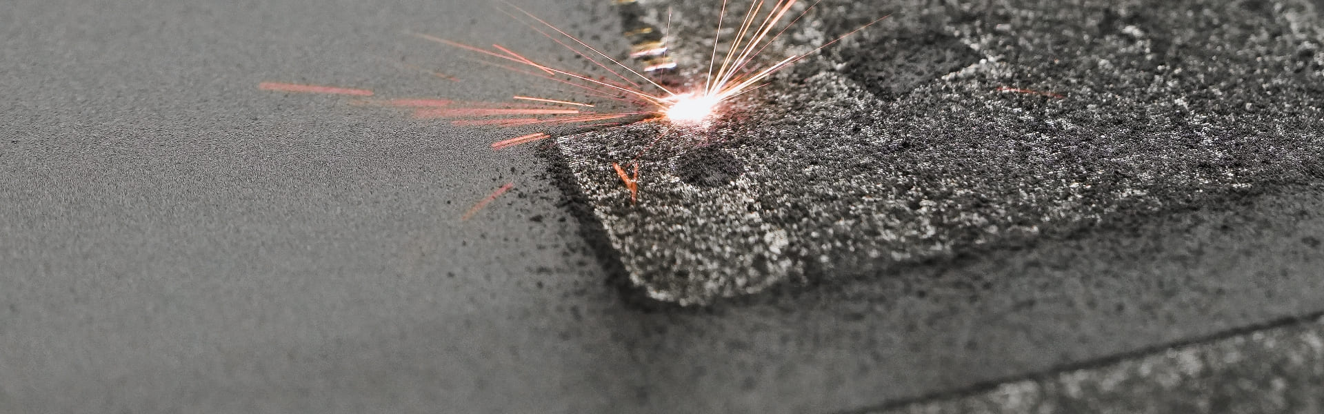
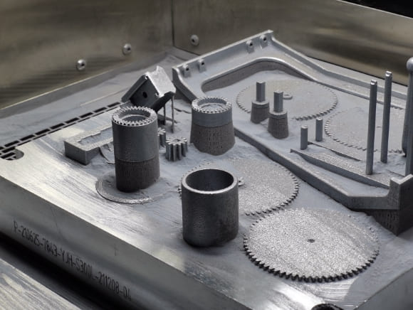
    Scanning the metal powder bed with laser light, the powder will be melted and solidified into metal parts. The density of standard metal parts printed by SLM is over 99%, while the mechanical properties of SLM printed parts are as good as those manufactured by traditional processes. Moreover, parts with complex structures or parts that need to be lightweight designed can be easily manufactured with SLM. Upload CAD files for instant quotes.

    SLM Capabilities
    Maximum Printing Size 320*320*400mm
    Lead Time 7 Business Days
    Tolerance ± 200μm or 0.2%mm
    Minimum Layer Thickness 1 mm

    * For expedited lead times or parts that exceed the maximum printing size contact hello@wenext.com

    Metal 3D Printing Material Options

    Below is available materials for SLM 3D Printing.

    Metal 3D Printing Material Options

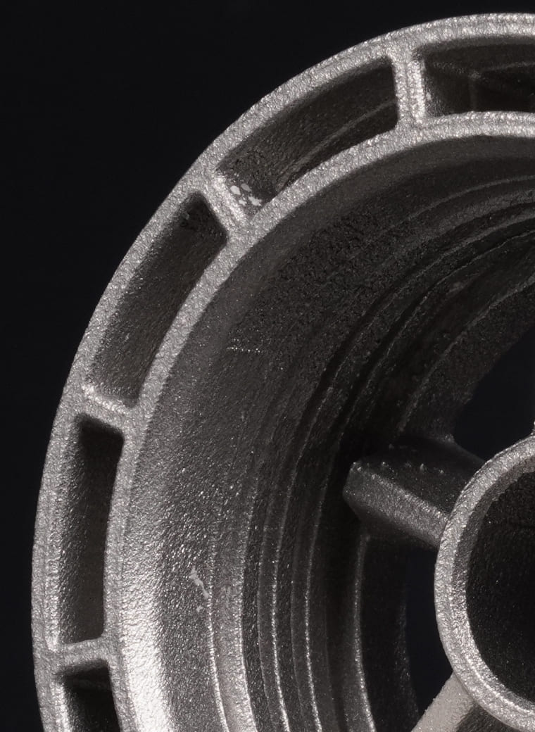
    https://oss.wenext.com/cms/images/services/3d/slm/service-3d-slm-316l.jpg

    SUS316L

    Color

    Metallic

    Tolerance

    200 μm or 0.2%

    Properties

    Finish: Pitted

    Note: Good mechanical properties

    Post Processing

    /

    Max. Printing Size (mm)

    320*320*400

    Download datasheet wenext

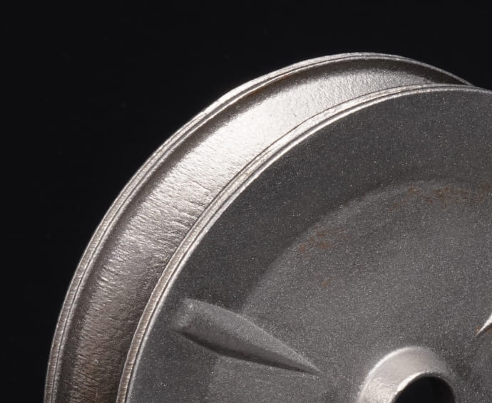
    https://oss.wenext.com/cms/images/services/3d/slm/service-3d-slm-AlSi10Mg.jpg

    AlSi10Mg

    Color

    Metallic

    Tolerance

    200 μm or 0.2%

    Properties

    Finish: Pitted

    Note: Good mechanical properties

    Post Processing

    /

    Max. Printing Size (mm)

    320*320*400

    Download datasheet wenext

    Design Rules

    Design Guidelines for SLM

    Material AlSi10Mg SUS316L
    Supported & Unsupported Wall Part Size -Minimum Wall Thickness

    5*5mm - 0.4mm

    10*10mm - 0.4mm

    50*50mm - 0.5mm

    100*100mm - 0.8mm

    200*200mm - 1mm

    5*5mm - 0.3mm

    10*10mm - 0.5mm

    50*50mm - 1.2mm

    100*100mm - 2mm

    200*200mm- /

    Minimum Hole Diameter Materials Diameter (vertical) 0.5mm 0.5mm
    Minimum Escape Hole Diameter Recommendation > 2.0 mm Diameter > 2.0 mm Diameter

    Minimum Vertical Post Thickness

    Supported Post 0.5mm 0.5mm
    Unsupported Post 0.5mm 0.5mm
    Width 0.2-0.3mm 0.2-0.3mm
    Minimum Embossed Detail Height 0.2mm 0.2mm
    Distance 0.3mm 0.3mm

    Minimum Engraved Detail

    Width 0.8mm 0.8mm
    Height 0.5mm 0.5mm

    Not sure about which process is the correct one for your part design? Download our 3D Printing Design Guidelines

    Surface Finishing Options

    Take a look at surface finishig options for metal parts.

    Standard Finish

    Standard Finish

    Sandblasting

    Sandblasting

    Polishing

    Polishing

    Post-Processing Capabilities for Metal 3D-Printed Parts

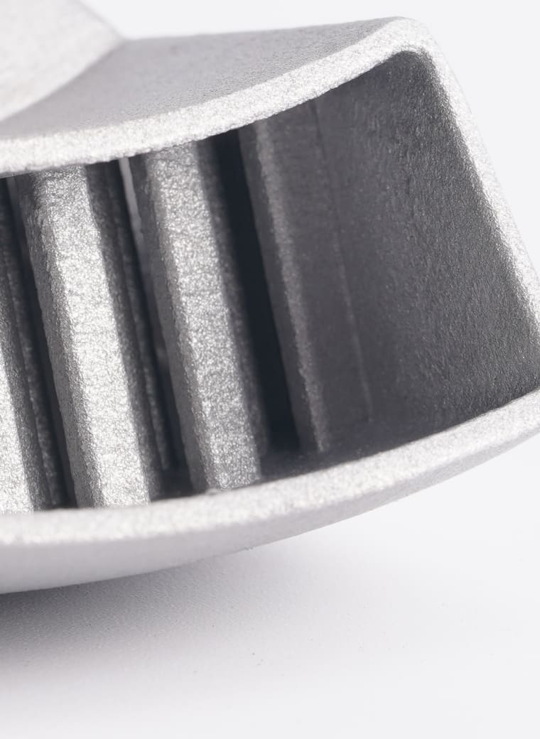
    We offer a variety of post-processing options to cater for different needs.

    Part Unloading

    When printing process is finished, the printed parts are surrounded by un-melted metal powders, which means it is necessary to separate the printed parts from the un-melted powders and remove the condensates and bigger semi-melted particles. This process is called part unloading that can be done either manually on the machine or through a vacuum powder conveyor module which prevents direct contact from the powder.

    wenext

    Depowdering

    The process of depowdering is to remove remaining trapped metal powder in the printed parts, which mechanical vibration can push the powder out of the printed parts. In such parts, any residual powder in the parts will hinder its functions. Additionally, if the part is heat treated without depowdering, the powder will be solidified, resulting in blocking the channels.

    Heat Treatment (Annealing)

    Heat treatment/ annealing is performed in a vacuum/ inert furnace. The heat treatment cycle is set according to the chemical composition of the material. Heat treatment reduces the internal thermal stress that occurs during printing and improves the mechanical properties of the printed parts. It is important to note that heat treatment is performed before separating the part from the build plate to avoid warping.

    Part Cut-off

    After finishing heat treatment process, it’s time to cut off the printed parts from the build plate. There are mainly three ways to deal with the cut-off process, which depends on the parts structures and supports.

    1. Manual Chiselling

    When the supports of printed parts are weak and minimal, chiselling out the supports can be applied.

    2. Bandsaw

    Bandsaw cutting requires printing about 5mm of additional material to compensate for blade thickness, which means it will increase the cost if printing large volume materials. Also, bandsaw is not precision cutting. Therefore, the cut surface must be machined for a better surface finish.

    3. Wire EDM

    As the easiest and most precise method of cut-off, the cut-off line is only 0.2mm diameter, and extra material with a thickness of only 0.25mm needs to be printed to compensate for the wire diameter.

    Support Removal

    By separating the printed parts from the build plate, it is easier to remove remaining supports on the parts.

    1. Manual chiselling is the common way to remove supports. However, the surface finish of the support-removing area needs to be improved if using manual chiselling.

    2. For surfaces with underlying supports that require a 2D profile with a good surface finish, using Wire EDM to remove supports is recommended.

    3. For complex surfaces with supports beneath and requiring good surface finish, using CNC machining to remove supports is recommended.

    Machining

    Printed parts may require machining such as thread for fastening, holes for mounting a shaft, or a flat surface for butting. Part-specific Jigs and Fixtures are manufactured to clamp the part if needed.

    Surface Finishing (Sand-Blasting)

    Select the surface treatment technique by the desired type of finish and aesthetic appearance. Surface treatment technique includes vibro tumbling, shot blasting, abrasive flow machining, plating, polishing and micro machining.

    Inspection

    The final stage of post-processing is inspection. There are three types of inspection applied.

    1.CMM. Utilize CMM to make sure the dimensions are meeting the GD&T of the 2D drawings, and CMM report can be released if needed.

    2. Mechanical inspection. Testing through laser scanning to ensure that the mechanical properties such as tensile, shear, microstructure, density and hardness is meeting the material datasheet.

    3. Structural inspection. Using tests such as dye penetrant inspection, ultrasonic testing and CT scanning to ensure that the printed parts are free from surface cracks or porosity.

    From Idea to Products

    Get Your Instant Quote wenext

    Copyright © 2023 Wenext, All Rights Reserved

    This website uses cookies for better personalized services. By using our websites, you agree to this use. Privacy Policy

    We use cookies to improve your experience, check out Privacy Policy.